Often the phrase “Fixing the phase” or “Flipping the phase” (or more correctly, “Flipping the polarity”) is used in audio production. What does that mean? Why would you attempt to do that? When should you look for problems? How do you do it?
I’m going to try and cover these questions starting from the very basics. This includes scenarios without physical recordings, so you electronic musicians may get something out of it too!
Let’s get started.
Contents
What
First we need to arm ourselves with some basic concepts. I’m going to break these down without any complex math. Just a visual and ‘intuitive’ method of understanding the subject.
I’ve taken some minor liberties with mathematical purity in the explanations to help the reader better understand the practical implications of the subject.
What is Phase
The first thing that we need to know is: What is phase. I covered this once before, but I’m going to do it again. This time slightly differently. (I will be discussing using degrees as the angular measurement. I’ve discussed this with dozens of people, and their eyes glaze over when using radians, so I have learned to stick with degrees.)
Let’s start with a circle. Hopefully you remember from school that your position in a circle can be described as an angle in radians or degrees. When working with audio though, we think of sine waves. Luckily there’s a relationship between circles and sine waves; they are the same thing expressed differently.
A sine wave can be thought of as an “unwrapped” circle. Look at the animation above. I start with a circle, then unwrap it in to a sine wave. We can think of a sine wave as being a circle that’s unwrapping over time. The “over time” part is important!
As we move down the sine wave, the current phase value changes. We can think of phase as our position in the sine wave. 1/4 of the way through our sine wave and we’re at 90° phase. Half way through the sine wave we’re at 180° phase. 3/4 of the way and we’re at 270° phase. All of the values in between apply as well.
Since our phase measurement changes as we move, we can recognize that phase is proportional to time. As time changes, so does the phase of a periodic signal. This also means that if we know the phase of the signal over time, then we know how fast the phase is changing. What do we call how fast a signal changes? Frequency. So we know that the phase at X time is relative to the frequency of the signal. For a periodic signal starting at 0° offset, if we know the any two of these three things, we can figure out the third: time, frequency, phase.
Sometimes the signal doesn’t start at 0° though. We call that the starting phase. It’s irrelevant for this discussion, but when working with synthesis the concept is important. We could more accurately say that if we know 3 of these 4 things, we can figure out the fourth: time, frequency, starting phase, phase. For periodic signals we can figure out the starting phase if we know the phase delay, and vise versa.
To recap: Phase is simply our current position in a single component sinusoidal signal. We’ll see why that matters soon.
What is Phase Delay?
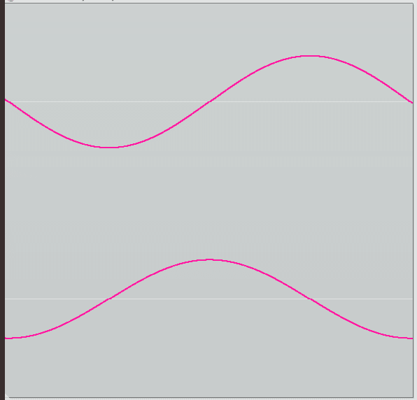
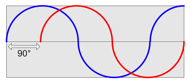
What if we want to change the phase of our signal? We can just introduce phase delay. We can think of this as adding or subtracting something from our ‘current phase value’. For a 90° phase shift, we can think of adding 90° to every phase value. The actual DSP/Electronics are slightly more involved, but that will suffice for thinking about the process.
It’s really that simple.
In the image above we’re changing the phase of the signal by 90°. As we trace the sine wave with our eyes, we shift every value by 1/4 of the signal’s period, or 90° (because 90° is 1/4 of 360°, and 360° is the total ‘number of degrees’ we have in our sine).
When we’re at 0° in the original signal, we’re 90° in the changed signal. When we’re at 47° in the original signal, we’re at 137° in the changed signal, etc…
What is Polarity
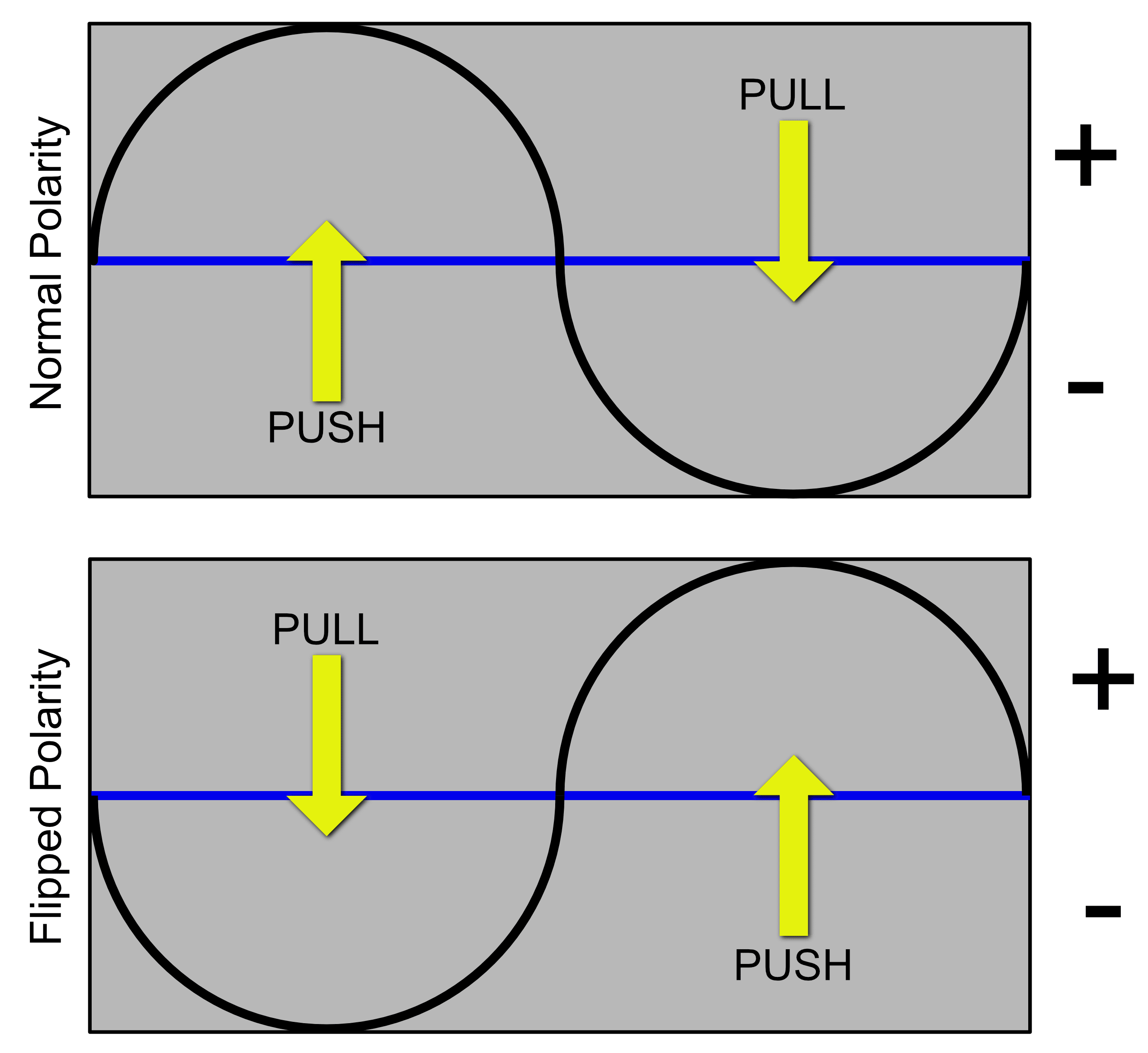
Audio is primarily thought of as an AC system. That means that we think of our base point as being 0. From there the signal is either being pushed above zero or pulled below zero. The signal has either a positive influence or a negative influence.
What happens if we switch the “pusher” and the “puller” influences though. We feed the same signal, but when it should push it pulls, and when it should pull it pushes? We’ve inverted the polarity!
If we have a very complex signal and we invert the polarity, then everything is the same except it gets turned upside down. The push/pull get exchanged and we’re flippity-floppity-bippity-boppity with some jello putting pops.
Changing a signal’s phase by 180° is identical to a polarity flip, but with polarity we are simply flipped or not. With phase adjustment we have all of the in-betweens.
What is group delay?
Oh look, I covered this before sorta. Let’s try again.
The first thing we must understand, and I mean that you must fully grasp this, is that every finite signal can be thought of as a summation of sine waves. When you look at a spectrum analyzer that is what you are seeing. You are seeing the amplitude of each sine wave, for a given frequency, at some point in time. A look in to what phase is, and how it can affect your audio productions.
So if our signal is a summation of sine waves, then we have a lot of phase values in there. Sometimes we want to know the difference between 2 signal’s phase. Most often this difference is taken in the context of before processing and after.
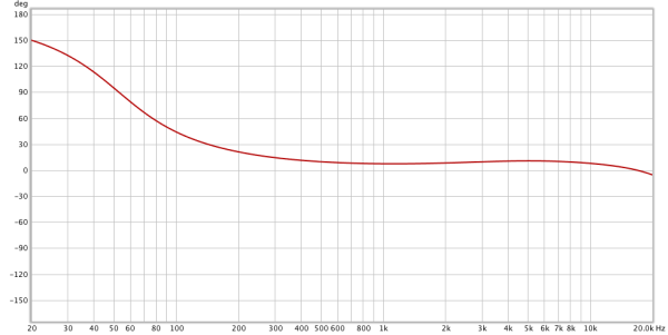
Every frequency may be rotated differently, so how do we visualize this? With a bode phase plot.
The X axis is the frequency, and the Y axis shows us how much phase delay has occurred compared to the original signal. In our graph above 50hz is rotated by about 90°, but 200hz only is changed by about 22°. The phase change across the spectrum isn’t the same.
This is important! Many processors change relative phase, but not equally across the spectrum. You may later be working on something with phase/polarity adjustment, but then ruin it all with an EQ or some other processor. OR maybe a simple EQ adjustment is enough to fix an issue?
Time
We know that phase is our position at some point in time. What if we change the time though?
Delaying a signal offsets the relative phase between the original signal and the delayed signal. It seems simple enough, but it’s not so simple.
Phase is relative to the rate of change, or our frequency. If we have a 10hz signal and want a 180° phase change via time adjustment, then we’d move it by 50ms (half of the time it takes for 10hz to cycle: 1000ms / 10hz / 2). We learned that complex signals have lots of sine waves though, and that complicates things.
If we have a mix of a 10hz sine wave and a 6hz sine wave, then shift it by 50ms what happens? The 10hz waveform is 180° shifted relative to the original, but the 6hz waveform is only shifted by 108°! The 6hz waveform doesn’t change phase as quickly, so in 50ms it only gets to 360 / ((1000 / 6) / 50) = 108° of rotation.
If we wanted to “fix” this signal, it could be difficult to figure out the exact group delay (rotation per frequency). Since one signal was delayed, if we have access to that signal we can move it back in time somehow, or move the other signal forward in time to “fix” our issue.
Sometimes time adjustments are the way forward. (pun intended, you’re welcome)
Why
Why should we mess with phase and polarity at all? What are the things that we could solve with this knowledge?
Maybe more importantly; what things can we screw up with this knowledge?
Why adjust phase?
Once again, I already covered this partially before. Check out the example to quickly investigate an example of how relative polarity and phase can make some major changes. I also have another example here of how phase changes can have drastic effects on your audio.
But hey! Let’s do it again, but this time a bit differently.
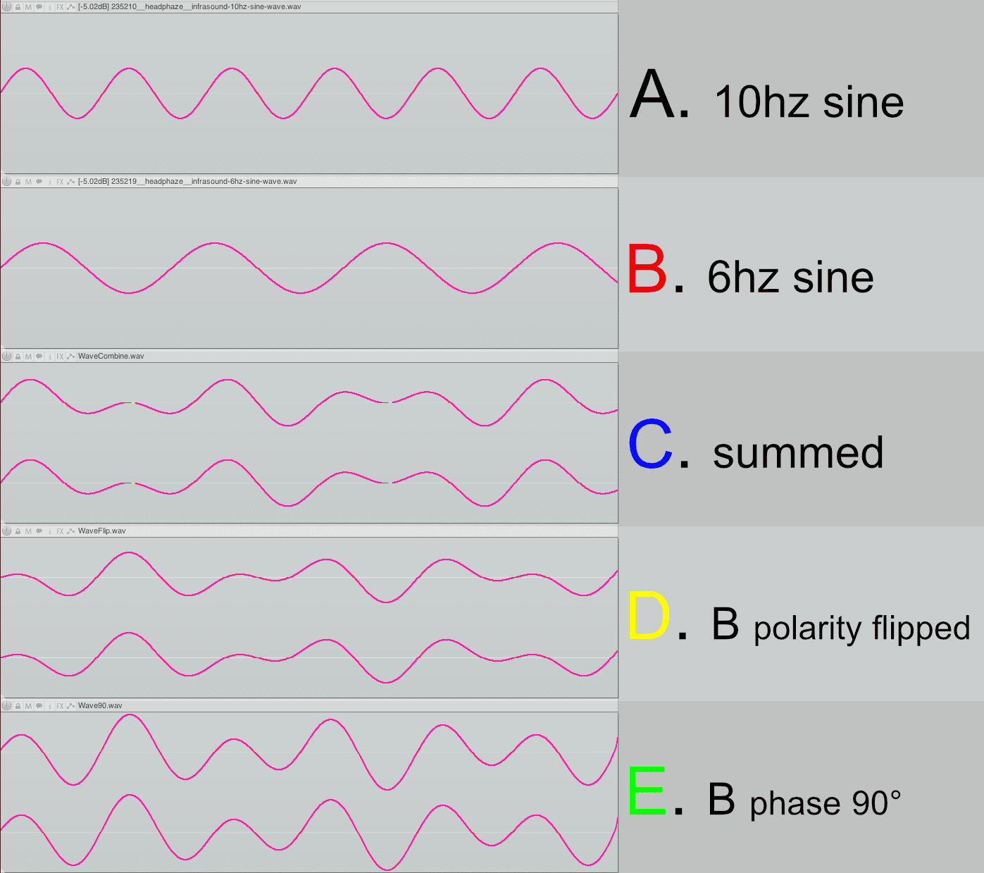
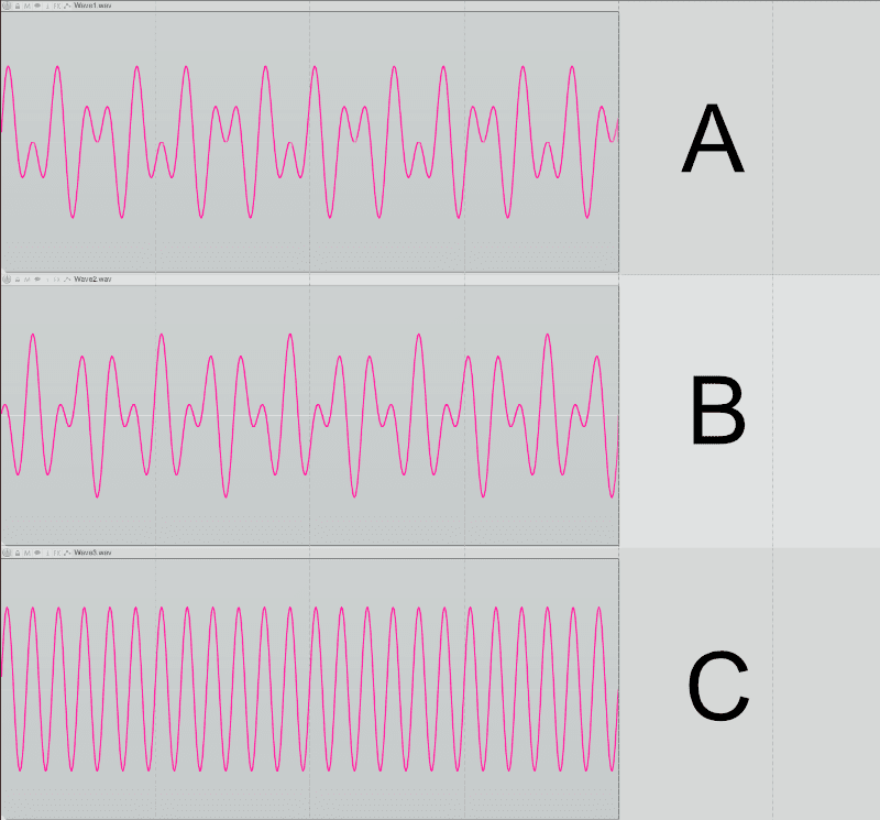
Let’s refer to our image above. I have 2 sines: one at 10hz and one at 6hz. Those are files A and B. The next 3 files are:
- C - A and B mixed together.
- D - A and B mixed together, but B was polarity inverted
- E - A and B mixed together, but B was phase rotated 90°
I’m sure you can see differences between C, D and E even though they are all sums of the same 2 waves. Let’s investigate further. Here is some information about C, D and E (I use the program Sox with the command sox file.wav -n stats to get this information):
- C
- Pk lev dB = -4.65
- RMS Pk dB = -7.23
- D
- Pk lev dB = -4.00
- RMS Pk dB = -7.17
- E
- Pk lev dB = -0.47
- RMS Pk dB = -3.44
Flipping the polarity of one of the components didn’t change much in this example, but there is a difference. C (sum) and D (sum, one flipped) are pretty close in value to each other. The polarity inversion of one signal in D did cost us about 0.5db of headroom though, since the peak is higher.
The big surprise here is when we adjust the phase of one component by 90°. E (sum with 90° shift on one) increases the peak level by 3.5db! The RMS also goes up by about 3.5db. That’s a huge change. If this was 2 snare drum mics and those frequencies were the constituents of the attack, we’d have a much punchier snare drum if we could rotate the phase of one mic by 90° (in this example).
Or what if we were working on a master? Even though C, D and E are all the exact same frequencies, E has far less headroom. We could perhaps adjust the phase of a part of our mix and get back a little bit of headroom without changing much else.
When
When do we need to be aware of potential phase issues? Anytime there’s 2 signals that are similar which are being summed.
This has some caveats though. Let me elaborate
Microphones
Any time that you have 2 or more microphones capturing the same sound source, there will be a potential for phase issues when those 2 signals are mixed.
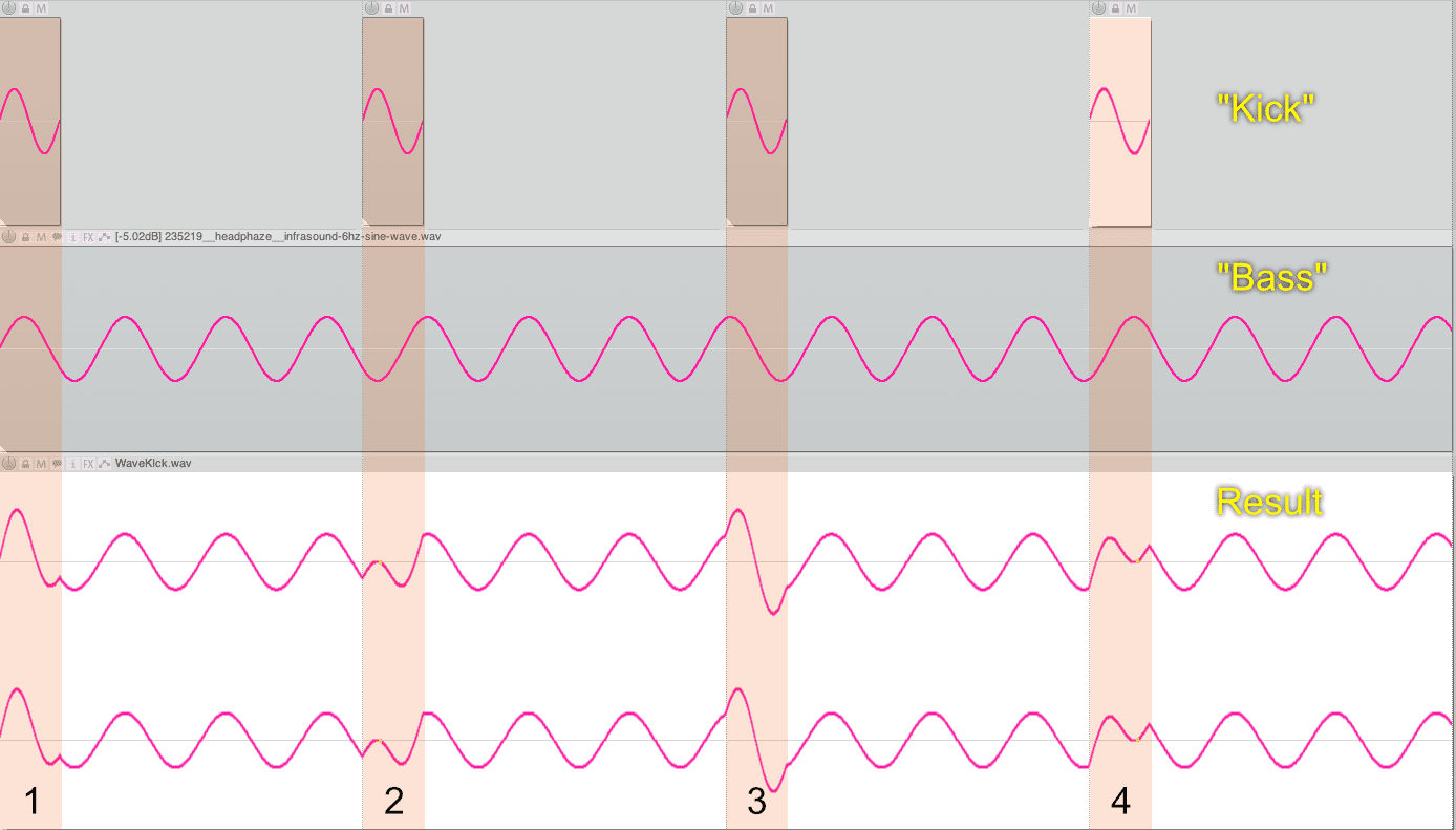
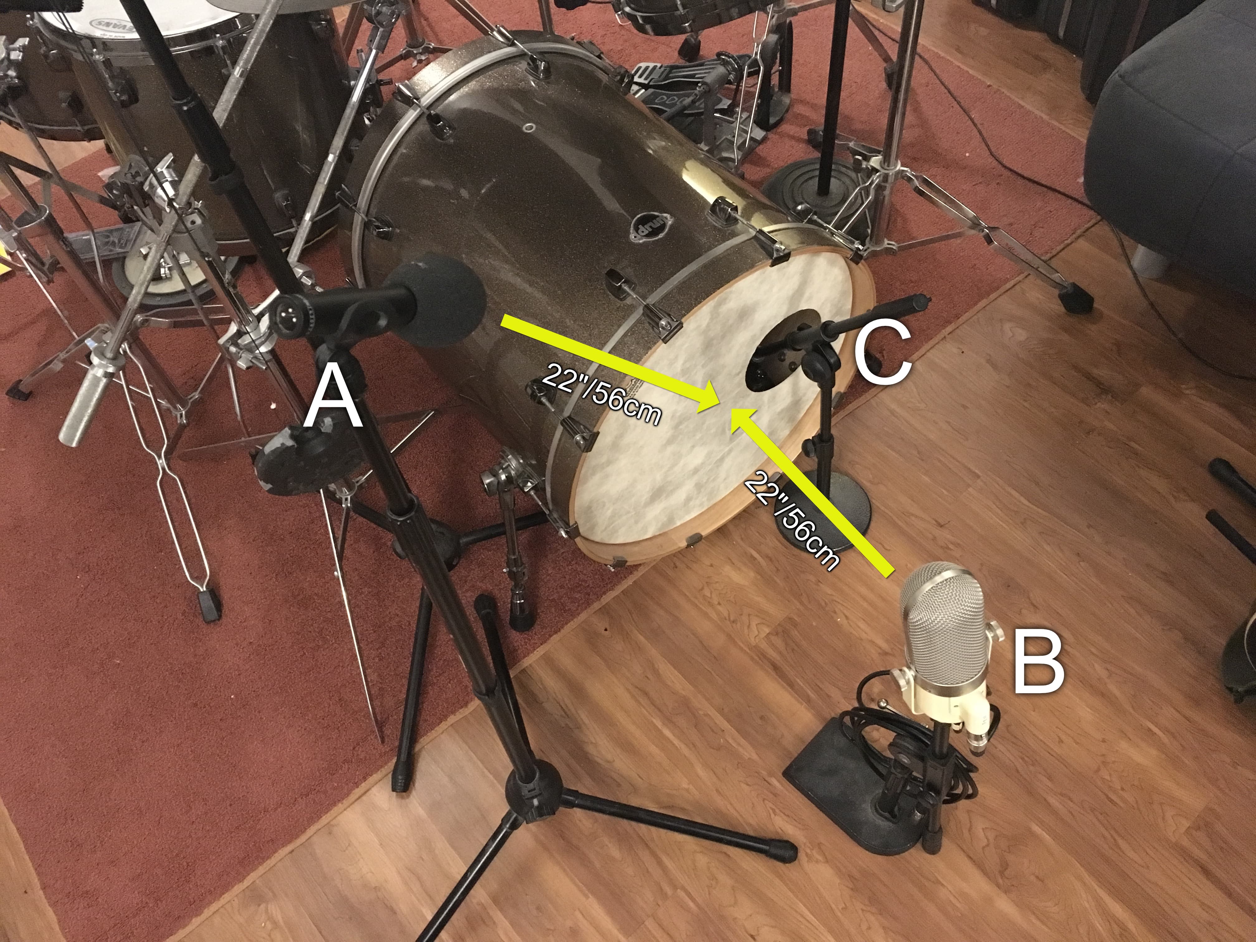
Let’s look at this hypothetical kick drum mic setup. I have 3 mics here: one inside the kick drum and 2 outside the kick drum.
When the kick drum is hit, mic C gets the sound before mic B gets the sound. B gets the sound about 1.6ms later than mic C. We learned that time changes can affect phase, so that means that we could be weakening our sound with phase cancellations, but we could also be making a beefier sound with correlated summing of frequencies. We’ll learn how to tell what is happening later.
What about mics A and B? They are the same distance from the center of the kick drum right? Yes they are. The issue here is that they are recording different sounds. Mic B gets the initial burst of air from the drum head, while mic A gets mostly shell sound.
The mix of A and B may once again have phase issues due to the differences.
These issues happen all over the recording of a drumset, but they can also occur any time that you have 2 microphones that capture the same sound and are subsequently mixed. Guitars, choirs, pianos, anything stereo etc.. That mixing may happening in a mixer/DAW, or it may happen in the air in the case of stereo mics, but it happens.
Layering
Another scenario that’s common is when layering sounds. If there’s 2 sounds that are always being summed with a similar frequency. This one is tricky though.
The two sounds may not always have the same phase relationships. If you layer two synth sounds the starting phase of the oscillators may not always be the same, the filter may change value, and all sorts of others things may change from note to note. A phase cancellation happening at 100hz on one note may be a peak the next played note.
There are times though where it can matter. If you’re using the same sound and using parallel processing for instance. This may happen with things like Aux sends or any other method where you mix the original signal with an affected signal.
If you are layering sounds in stereo then you may wish to be extra careful of in-air stereo interactions, or interactions between components that are not hard-panned.
When it’s hard to deal with
Sometimes there’s really not much you can do. I have an example above demonstrating it.
I have setup a fictional example of a kick drum and a bassline. The third track shows the result of summing them.
The frequency of the kick and bass are not the same. The bassline doesn’t “reset” on each beat, so the starting phase on each beat isn’t exactly 0°. The Kick sample does start at 0° each time though.
- The first hit has a nice peak. This probably sounds like a nice hit.
- The second hit is really weak. Both the kick and the bass nearly disappear!
- The third hit has a another nice peak. This time it looks sharper.
- The fourth hit is weak again. It’s not exactly like the second hit though, and this one has a pronounced click sound.
So what do we do!? Cry. That’s what you do, you cry.
We could try rotating the phase a bit to get an average amount of punch from every kick hit. Even better would be changing the kick sample or the bass sound. Better still would be re-arranging the sound so the kick and bass aren’t always headbutting each other.
If these were more complex signals, then we may be able to alleviate issues with other processing, but that’s beyond the scope of this post. Obviously when you change things… they change, but we’re only concerned with phase adjustments on a simple level here.
Stereo
Maybe you’ve heard someone suggest that you should check your mixes in mono. They want you to make sure that if the Left and Right signals are combined, that there would be no major phase differences that could cause significant cancellations.
This also applies ‘in the air’. If your right speaker is outputting an inverted polarity signal from the left, it will sound weird and hollow. There will be no phantom center image, and your brain will interpret this as being a wider sound than otherwise.
Not all signals are just left or just right though. Sometimes we pan signals partially left and partially to the right. That means that portions of the signal will be summed, and subject to phase-demons.
Let’s look at the image above. Assume that A is the left channel and B is the right channel. What do you think happens if we combine those complex signals?
Oh. We just get a simple sine wave in C. The rest of the waveforms that made up that complex signal vanished and we’re left with nothing but a 10hz signal.
This can happen with your stereo signals. It can be a total cancellation like above, or a small difference. An entire instrument can disappear or just some part of the spectrum will change.
How
We know what phase is. We know that sometimes we need to mess with it. We probably don’t know when, but let’s see how.
Looking for problems
We need some way to monitor changes as we adjust. This doubles as a way of finding where issues exist. Ideally you will develop an ear for this sort of thing, but I’m going to explain how you can see these issues.
The easiest way is to use a correlation meter of some sort. A Goniometer is a common way. A phase correlation meter is another easy way. Spectral Analysis is another way. A frequency correlation meter is the best way.
If you are working with stereo then you can use these tools as intended with no specific routing.
Goniometer
Using a goniometer (sometimes called a vectorscope) is one way to check the phase of two signals.
This graph is showing you a plot of each sample’s relative phase. Center is perfectly correlated (or a “mono” signal in stereo). A horizontal line is a perfectly uncorrelated signal (or the “side” signal). 45° line to the left is a signal panned hard left, 45° is a signal panned hard right.
So how does that help us get an idea of the phase relationships between two signals (that aren’t part of a stereo signal)? We use one signal as ‘left’ and one signal as ‘right’.
Create a bus or send. Put a goniometer or vectorscope on the track. Pan one track hard left, and one track hard right and feed those to your goniometer track. The result is showing you the phase correlation over time of the 2 tracks.
If there is a perfectly straight vertical line, then the 2 signals are perfectly in phase. They are the same signal.
If the signal is a perfectly straight horizontal line, then the 2 signals are 180° out of phase from each other (or one has the polarity inverted).
Everything else in between is showing you the correlation over time.
What is our goal? Our goal usually is to have a mostly vertical line, but that’s often not totally possible. If you have a phase adjustment plugin (we’ll discuss some in tools) then you can rotate the phase of one of the signals and watch. Often there will be a clear change towards ‘more vertical’ as you rotate the phase of one of the tracks. That indicates higher correlation.
In the video above you can barely make out what’s happening, but with some practice it becomes a lot easier. I setup my signal as described with 1 track going to Left and one track going to the Right. Then I used a phase rotation plugin to sweep the Right signal back and forth till I recognized a clear line amongst the chaos. I listened and aligned. Done.
When I checked with my correlometer, it turned out to be within 10° for the whole signal. I even surprised myself a bit.
Correlation meter
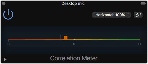
A correlation meter is another method. This shows you an average over time of the correlation between the two channels. A value of +1 is perfectly correlated. A value of -1 is no correlation. A value of 0 is either hard pan or a 90° difference.
Once again you use your phase/polarity tools to make changes and watch the correlation meter. Most meters show +1 as the most correlation. Some meters show correlation with the value centered. Consult the manual or test yourself to be sure.
Spectrum analysis
I’m not really going to cover this. It’s fairly unreliable. Sometimes you can make out very small changes in the spectrum of a signal that improve as you adjust the signal.
More often though it’s just a guessing game. Real time analyzers are subject to limitations that make using them for monitoring phase interactions of signals an academic exercise at best.
Though it must be said that most automatic time alignment products use spectral analysis to do their work. So it is possible, it’s just not practical for the average user
Correlometer
The best way to see what’s happening is to use a proper correlometer that shows the relative phase for various frequency bins.
The video above is Voxengo PHA-979.
I discussed before how frequency and phase are intermixed, and the results of changing a single component. Likewise when measuring phase relationships it’s best to know these relationships across the frequency range. Two practical examples on a snare drum:
- High correlation around 2-5khz will yield more ‘snap’ in the sound.
- High correlation around 200-500hz will yield more ‘body’ in the sound.
It may not be possible to easily adjust the phase of the signal, without fuddling with the group delay, so that you have perfect correlation across the whole frequency spectrum. So you may have to choose what parts of the spectrum have the highest correlation.
You can even think of this as a way of EQing your combined signal without actually touching an EQ.
The video above is a Correlometer showing a signal that has some fairly significant deviation around 200hz-1khz, th en with the phase adjusted. This is a snare drum, and without the phase change it sounded rather weak. Phase adjustment gave it an audible increase in body and peak value.
Fixing Polarity
Fixing polarity is easy, especially if your DAW does it for you.
Use one of the tools above and your ears (most importantly your ears!), and use a polarity flipper to make adjustments until things sound better.
If you’ve read my DAW Reviews then you know how annoyed I am when polarity inversion is a plugin and not built in to the mixer. Maybe you’re starting to understand why, especially since I do so much recording of musicians with microphones.
Fixing Time Delay
Often there’s just no way to make a phase adjustment that will do the trick because the issue is that the 2 signals are delayed from each other too much. So you need to adjust the timing.
In most DAWs you can zoom in to compare the two waveforms. Align the largest peak to the largest peak and you’re probably done.
There are tools that can enhance this process though.
Fixing Group Delay
Fixing group delay isn’t particularly easy in your classic studio environment.
Non-Linear-Phase filters introduce group delay. This includes your common EQ, various filters, allpasses used in reverbs and phaser, and even delays. However all those methods bring other side-effects beyond phase changes.
There is an easily accessible trick to mess with group-delay though: crossovers.
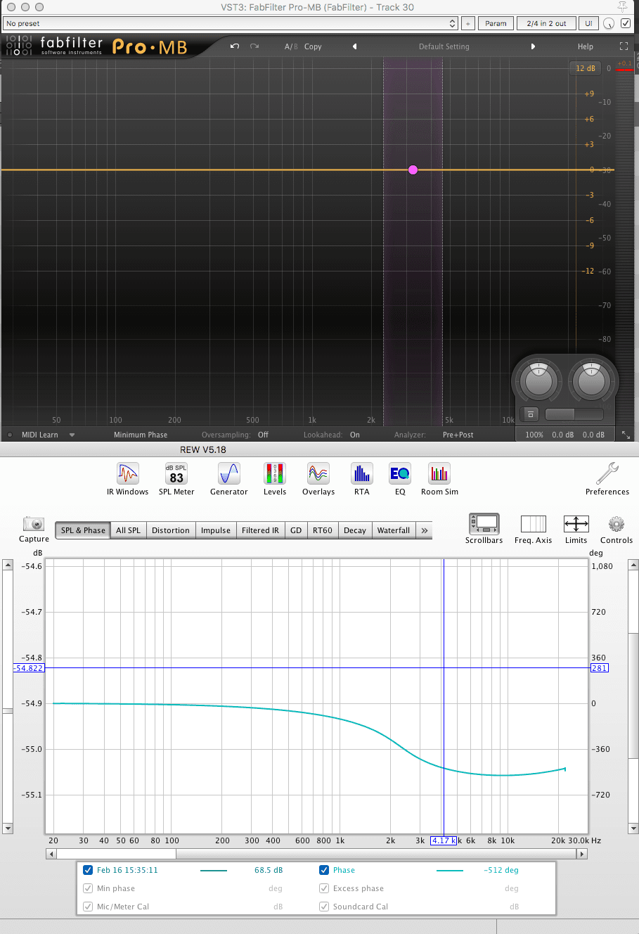
The concept of a crossover is that you split the audio in to separate bands for processing, but the unprocessed sum of those bands has the same spectral balance as the unprocessed signal. If we use filters that introduce phase changes for our filters, we have a crossover that changes the phase but doesn’t change the frequency response.
In the image above I have a multiband compressor (Pro-MB, importantly set to minimum phase mode!) with 2 crossovers set. The rest of the plugin is set to do no processing. Threshold of 0 and a range of 0.
On the bottom though we can see that the relative phase of the output is rather different! At 1.4khz we have a total 180° phase rotation. At 50hz we have effectively 0° of rotation.
Unfortunately this requires some experimentation. This methodology doesn’t give you instant “I want X frequency rotated to Y”. It is a fun hack though which can be useful sometimes.
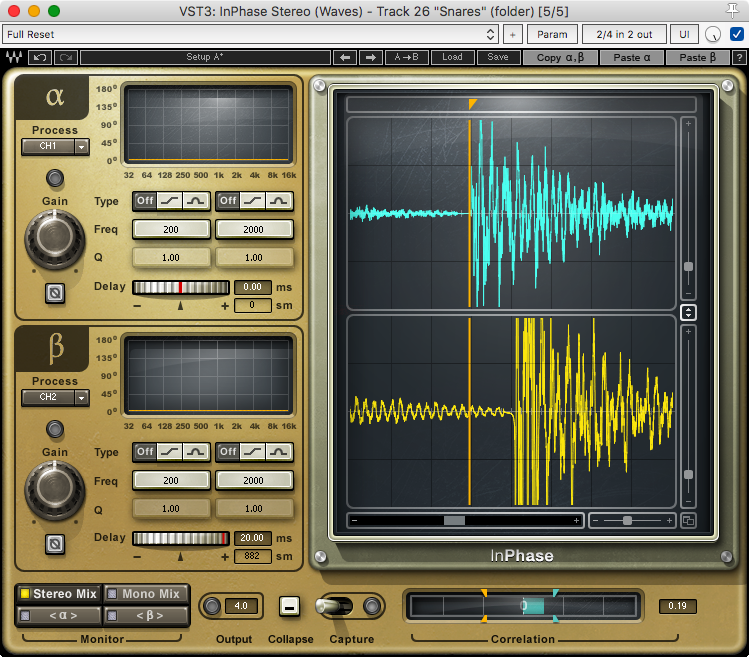
You’ll probably need to buy something like InPhase which has variable allpass filters if you really want to delve in to frequency-specific phase adjustment. Melda MFreeformPhase is another interesting plugin for group-delay changes, and it’s free.
Tools
Tools! We need ways to do things. First you should check if your DAW comes with a correlometer, goniometer, vectorscope, simple delay, any sort of stereo meters etc…
See what you can do with what you have. Then maybe explore some other options.
Third-Party Tools
This is not an exhaustive list by any means. These are just some tools that can help:
- Voxengo PHA-979 - An excellent product. It has both time delays, phase rotation, polarity inversion, a correlometer and a few other metering options. In the context of this article, PHA-979 is king.
- Little IBP Phase - Phase rotation, time adjust, polarity inversion and other tools. No fun metering though.
- Waves InPhase - In phase offers a much nicer way to handle adjusting delays. It also has filters that allow frequency targeted phase rotation.
- Sound Radix Auto Align - Auto Align fixes time delays automatically and can also adjust polarity.
- MAutoAlign - Similar to Sound Radix Auto Align.
- MFreeformPhase - Allows you to change frequency specific phase as needed. FREE
- Precision Time Align - a sub-sample time adjustment plugin.
- Flux Stereo Tool - Phase correlation meter with polarity inversion and volume adjustment.
- Signalizer - A set of metering tools for Windows, Mac and Linux. FREE
- X42 Meters - More metering tools. Either LV2 only or available with Mixbus. I reviewed this previously.
- Sonic Visualizer - A suite of audio forensic tools. Not a plugin, but exceptionally useful regardless. FREE
- Hofa Goniometer and Korrelator - A goniometer and correlation meter plugin. FREE
There’s many more tools out there. If you feel that I missed anything special then let me know in the comments and I will update this list.
Google is your friend. Use it!
Reaper Tools
Reaper has a few awesome free tools.
- JS: Phase Rotator - phase rotation plugin, comes with Reaper.
- JS: Goniometer - comes with Reaper.
-
JS: Channel Polarity Control - automatic polarity monitoring, comes with Reaper.
- Phase match selected items (check polarity) - Automatically fixes polarity for the selected items so they have the most correlation. Via Reapack (MPL)
- Phase match selected items (shift positions) - Adjusts relative time for selected items so they have the highest correlation. Via Reapack (MPL)
- Phase Alignment Trick - The REAPER Blog has a cool video explaining how to manually time align files using folder tracks in Reaper.
I’m going to cover one tool specifically though, because I find it so useful:
Stereo Alignment Delay
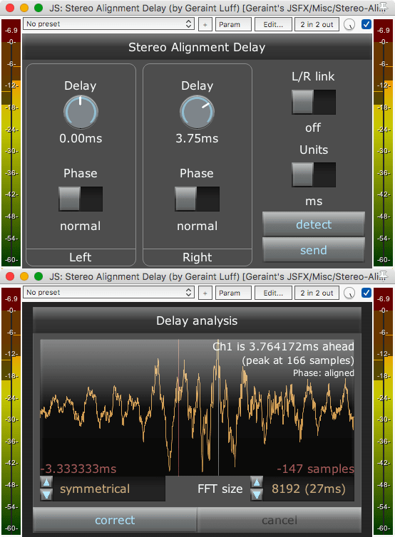
This is a script by Geraint Luff. It has two functions.
You use it to correct the stereo correlation of a signal via time adjustment, or you can use the send/receive modes to relatively adjust 2 tracks.
Stereo fixing requires that you hit ‘detect’ and it brings up a window. This shows you an FFT. You can click and drag to select an area to focus the analysis on. Press ‘Correct’ when you’re done and the delay time is set automatically.
Track relative is a bit more work.
- Put one instance of Stereo Alignment Delay on track 1. Put it in to send mode by pressing ‘send’
- Put another instance on track 2.
- Press ‘detect’ on track 2 and operate as you would for a stereo track.
You can change if the sending track or the receiving track is being adjusted by flipping the switch on the ‘send’ instance.
If you are working with mono signals then make sure L/R link is on.
I’ve found this to be a fantastic tool, and rather accurate.
Support Me!
This post took 6 hours to research, photograph, write and edit. If you appreciate the information presented then please consider joining patreon or donating!